Building a model Improved Ericsson Hot-Air Pumping Engine

This model is a 1/4 scale reproduction of an 8″ bore Improved Ericsson Hot-Air Pumping Engine dating back to the late 1800’s. It is nearly identical to the full size original 6″ Ericsson that I have in my collection. The model is in the form of a kit containing most of the major parts as unmachined castings straight out of the foundry, and a set of blueprints. As with my 1/2 scale Olds engine and 1/4 scale Mery engine, all machining, fabricating, finishing and painting, as well as assembly must be done to produce a usable engine. The engine itself went together quicker than I had anticipated, but the display became much more elaborate than I had expected, and took much more effort. All in all, a fun project!

The first cut of the project; facing the top of the leg assemblies. Without any flat areas to clamp to, these were a little hard to hang on to!
In the mill, the cylinder casting gets surfaced, bored and prepped for the cylinder sleeve. Once all the prep work is done, the steel sleeve will be pressed into place, forming a water jacket between itself and the walls of the casting.
One of the final operations on the cylinder, tapping the outlet for the water jacket. The flat boss with the 5 holes in it facing the camera is where the water pump will mount. Cold water is forced from the pump into the center hole, circulated through the water jacket, and then out the port on the side of the cylinder currently being tapped.
Turning the steel thick wall tubing down to the dimensions required for the cylinder sleeve. The inner diameter is honed to provide a smooth finish for the piston.
With the base plate, cylinder, legs and flywheel bracket finished, the unit starts to resemble it’s final look. The large casting underneath is the unmachined burner box. All the small steel and brass parts have yet to be fabricated, and several other castings have yet to be machined.
Here the rough casting of the flywheel gets a going over in the lathe. An expanding mandrel was used between centers to ensure the outer edge of the flywheel is machined concentric with the crankshaft that the flywheel will be later mounted to.
With small needle bearings pressed into the flywheel bracket on the engine and the crankshaft pin pressed into the flywheel hub, the rough finished wheel is fitted to the growing model.
The walking beam is supported by a bracket mounted to the top of the cylinder. Here the bracket is milled to later accept the bronze bearings the walking beam rides in. The pencil gives a feeling of the small size of these parts.
The initial work on the power piston. The basic piston casting is finished first, as seen to the right.
Originally, this piece was part of the overall piston casting in the real engine. For the model, this center piece, which acts as a guide for the displacer piston rod, is made separate and later attached to the aluminum piston by a special nut also needing to be fabricated. The connecting rods from the walking beam will attach to the power piston via two bosses milled into the center piece as seen to the right. For reference, the boss being machined is 1/2″ in diameter.
With the 4 major parts complete, the parts are assembled including the 6 miniature bolts to hold down the brass seal ring on top. The ‘bolts’ are 2-56 thread with 1/8″ (3.2mm) heads. The smaller threaded ring is the special nut to attach the center piece to the piston casting.
The walking beam casting being setup in the mill (left), further machining (center) and finally being mounted on the engine (right).
The first of the the 5 assorted connecting rods first starting out as a length of 1″ brass square stock (left), the walking beam end being milled (center), and the radiuses of the center section being cut on the first side (right).
The center area is milled to size (left), on the rotary table, the end radiuses are cut (center), and finally, the machined part fitted to the engine (right).
The water pump is built out of no fewer than 11 machined brass parts, some being soft soldered together when completed. The pump bore nut, shown at left on the rotary table, is the size of a 3/4″ nut with several machined surfaces inside. The finished pump, mounted to the cylinder is shown at right. The two tiny pettcocks, also shown at right, are used to drain the cylinder water jacket and release the air trapped inside the cylinder. The blueprints did not show these installed, but the idea and the measurements for their locations were taken directly off of my original full size engine. And yes, these pettcocks were bought, not built!
The engine is nearing completion at this stage. Here are left and right views of the assembly. The water pump linkage to the walking beam, finishing the burner box and some water pipe parts are the only major things left to do.
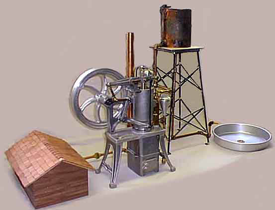
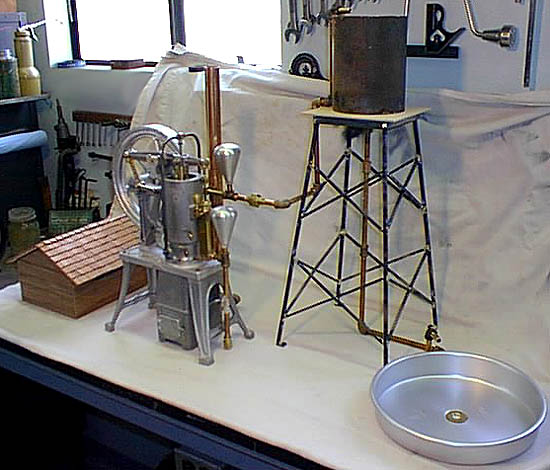
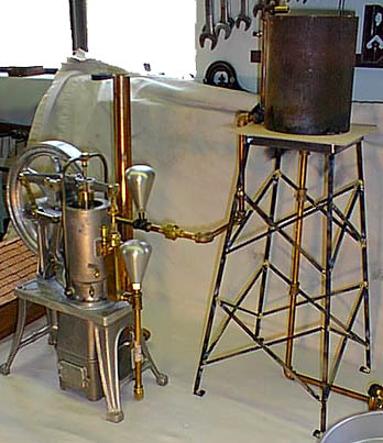
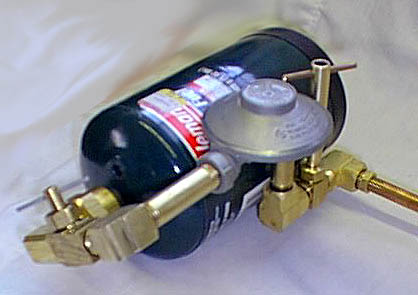
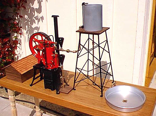
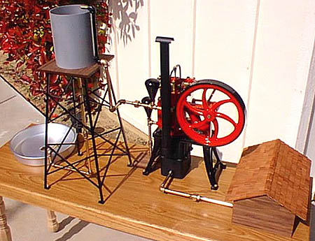
In order to display the model running, it’s necessary to have both water and fuel, in this case propane, as part of the display. The propane supply will be generally hidden from view, but the water will not only serve it’s purpose of cooling the engine, but will also show, in miniature, how the engine was originally used. For this display, a representation of a water tower and water trough are used. With two reservoirs of water and lots of pipe, it not only makes the display interesting, but also dissipates some of the heat from the engine. Here the display is roughed together to allow measurements to be taken.
A close up of the engine piped to the water tower tank.
A peek under the “supply shack” showing the propane tank, regulator and valves.
Finally, with all parts painted and piping installed, the display is finalized.
A close up of the right side of the engine.
The back side of the display.
The left side of the engine.
A close up showing the upper cylinder and water pump.

Project completed May 3, 1999

Scroll to Top