The Waterloo Boy Restoration Project

Phase 1 - First work done to Dec. 1, '97

A portion of this restoration I did back in late 1996, had to do with building a replica of the “Type A Waterloo 3/4″ Mixer”. Going strictly by the pictures in the Repair Parts List #16, I built what you see here as a modern version of the mixer. 90% of the parts are simple pipe fittings, while the remaining ‘Primer Cup’ had to be machined. Also, since right angle 1/4″ check valves and globe valves are very scarce, I modified two cast bronze tee’s to act as valves.
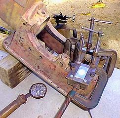
The babbit bearings, both rod and mains, all need to be redone. Here, the first of the main bearings and main caps are in the process of being poured. On the block, simple steel molds are positioned on each end of the bearing mount and are held in place with ‘C’ clamps. Any holes between the molds and block are sealed. The whole bearing area of the block is then heated to drive out any moisture and to allow the babbitt to flow properly. At the same time, the babbitt itself is heated and prepared. Then the babbitt is poured, filling the bearing cavity. The main caps are done likewise, but require a less complex setup. The whole process is about as hard to do as making lead sinkers for fishing!

One of the more major steps was to replace the governor gear and repair the governor shaft. The original shaft had been apparently broken and left shorter than normal (by at least 1/2 “), rethreaded with 3/8” pipe thread (along with the original gear), and the whole mess reinstalled in the governor bracket which had also been cut off with a hack saw. This put the fly-balls too close to the surrounding items, which they had also been modified! I machined the original shaft to take a newly fabricated steel extension which, in turn, accepts a newly fabricated replacement gear. The pin through the center also had to be fabricated. Shown here are all the components including both the new and old gears. Note the tooth missing from the old gear.

Here the actual cutting of the new governor gear is in progress. The gear blank is mounted on the new governor shaft extension that is acting as a mandrel. This assembly is rotated, one tooth position at a time, by an index head (large unit with handle just behind the 90 deg. mill head in left photo.) The right photo shows the “Involute” gear cutter cutting the gear blank below it.
Since all the governor parts had been moved from their original positions, it’s likely that this also led to the governor bracket being modified as well. Three stand-offs on the casting had been ground off and had to be built back up in order to properly re-align the gears. This was done with brass and then re-machined and ground to bring back the original shape. Also, the governor shaft bearing was milled out and a new bushing was machined and pressed in to take the ‘slop’ out of the governor.
Scroll to Top