The Waterloo Boy Restoration Project

Phase 4 - Dec. 22, '97 to Jan. 4, '98

The cylinder head is actually in pretty good shape with the exception that someone had bored and threaded a hole in the middle of it during the conversion to spark plug ignition. It was much more common to find the spark plug mounted in a plate covering the unused ignitor port.
After being sandblasted, the old spark plug threads were replaced with 3/4 x 16 thread. A piece of cast iron bar stock was machined to fit the hole and then threaded to match the 3/4″ thread. Cast iron was selected in order to have the same expansion characteristics of the head casting.
The cast iron plug is screwed into the head tightly and then brazed on both ends to seal the head and lock the plug in. Then the cylinder side of the head is machined flat and the outer side hand ground to match the exterior casting texture. With the internal surface brought back flat as original, the original compression ratio is also restored.
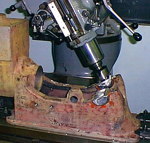
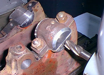
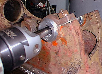
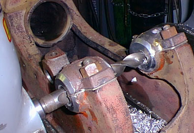
Back in the mill, zeroed with the cylinder bore, the main bearings are surfaced to take the re-babbitted main caps and shim stock. Again, the casting of this block is so bad that some of the rough babbitt from the pour did not clean up, though, nothing is really bothered by it. The right main bearing (off cam side) mount was almost a 1/4″ lower and canted compared to the left side. The two are much closer now, though still not exactly the same.
Once the sets of shims are cut and the main caps poured and faced, the caps are installed and torqued down. The real trick to this stage of setting the mill up is calculating exactly where to bore the mains. Alignment with the cylinder is obvious, but the distance between the cam gear mount and the crankshaft is also critical for proper gear mesh. This engine’s design also adds an angle to the equation, since the center of the cam mount is lower than the center of the crank.
After the initial bore is made in the first bearing, a boring bar with an adjustable boring head is used for the remainder of the cuts. The bearing is opened up to around .002 of an inch smaller than the final bore required by the crankshaft.
Once the cam side main bearing is bored, the harder to do ‘off side’ is started. With all the boring bars longer and of small diameters to fit through the first main, tool chatter can become a problem. Slower speeds and feeds usually will be the cure. Here, the initial material removal is done with a large drill. Once drilled, a boring bar will more accurately finish the job.
Scroll to Top